9. Adding Lighting to Games
So that's the theory; now
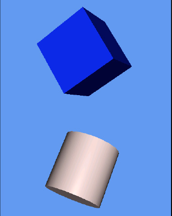
let's take a look at how we implement lighting in our game code. A screenshot from the project is shown in Figure 10.
9.1. Enabling and Disabling Lighting
The first thing that is needed is to tell the BasicEffect
object that we want to use lighting. Without this, all light features
will be disabled and ignored, as has been the case in our example
projects up until now.
Lighting is enabled by simply setting the LightingEnabled property to true when initializing the effect, as shown in Listing 3.
Example 3. Enabling XNA's lighting feature
_effect.LightingEnabled = true;
|
Lighting can, of course, be disabled by setting this back to false. This property can be updated anywhere within your game; it isn't restricted just to the Initialize function.
9.2. Light Configuration
Once the lighting system has
been switched on, the next step is to configure the lights. We have
three directional lights at our disposal, exposed via the DirectionalLight0, DirectionalLight1, and DirectionalLight2 properties of the BasicEffect object. Each of these lights has the following properties that can be used to configure its behavior:
DiffuseColor: the diffuse color of the light. Defaults to white.
Direction: a Vector3 structure indicating the direction in which the light is pointing. Defaults to (0, −1, 0), straight downward.
Enabled: a bool indicating whether this light is switched on or off.
SpecularColor: the specular color of the light. Defaults to black to disable specular lighting.
NOTE
All the light colors are represented as Vector3 structures. Remember that you can convert a Color to a Vector3 by calling its ToVector3 method.
The default configuration of the
lights is for light 0 to be enabled and the other two lights to be
disabled. As the lights point downward by default, this configuration
creates an effect similar to the sun shining from directly overhead.
Updating the light settings is
very easy because the parameters can be freely updated. To change a
light's direction or its colors, or to switch it on and off, simply set
the properties as required before rendering your objects.
The code in Listing 4
configures light 0 so that it is directed along the negative z axis. As
the user's viewpoint is also looking along the negative z axis in our
examples so far, this configuration results in the light illuminating
the objects from the camera position.
Example 4. Configuring a white light to shine along the negative z axis
_effect.DirectionalLight0.Enabled = true;
        _effect.DirectionalLight0.Direction = new Vector3(0, 0, −1);
        _effect.DirectionalLight0.DiffuseColor = Color.White.ToVector3();
|
For the light itself, this
code is all that is required to light up the objects within our scene.
However, we haven't done anything to set the normals for our objects
yet. Continuing to use the cube from our previous examples, we first
modify the class to use the VertexPositionNormalTexture
structure for its vertices. After setting the vertex positions as we
always have, we now need to set the normal for each vertex. For a cube,
the normals all point directly along the x, y, or z axis and so it is
easy to set these up manually. Listing 5 shows the beginning of the code to perform this task, taken from the Lighting project's CubeObject class.
Example 5. Setting the cube's vertex normals
// Set the vertex normals
        i = 0;
        // Front face...
        _vertices[i++].Normal = new Vector3(0, 0, 1);
        _vertices[i++].Normal = new Vector3(0, 0, 1);
        _vertices[i++].Normal = new Vector3(0, 0, 1);
        _vertices[i++].Normal = new Vector3(0, 0, 1);
        _vertices[i++].Normal = new Vector3(0, 0, 1);
        _vertices[i++].Normal = new Vector3(0, 0, 1);
        // Back face...
        _vertices[i++].Normal = new Vector3(0, 0, −1);
        _vertices[i++].Normal = new Vector3(0, 0, −1);
        _vertices[i++].Normal = new Vector3(0, 0, −1);
        _vertices[i++].Normal = new Vector3(0, 0, −1);
        _vertices[i++].Normal = new Vector3(0, 0, −1);
        _vertices[i++].Normal = new Vector3(0, 0, −1);
        // ... and so on for the remaining faces ...
|
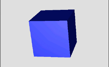
The cube's class is otherwise unchanged. Running the project displays a cube as shown in Figure 11. You can see that each face of the cube has its own color, determined by the light calculation that we have already explored.
Try experimenting with the light and material colors to see how they interact. The light color is set in the project's Initialize function (refer to Listing 7-17), whereas the object material is set against each individual object in its ObjectColor property. Thecube in the example project is added by the ResetGame function, and its color can be modified here.
As additional lights are enabled,
XNA has additional work to do to calculate the light for each vertex
within the rendered objects. For this reason it is important to disable
lights when they are not required. Lighting is a relatively inexpensive
calculation, so feel free to get your lights set up exactly how you need
them for your game.
9.3. Ambient Light
To use an ambient light, simply set the BasicEffect.AmbientLight property to the required color. All the objects rendered will take the ambient light into account.
9.4. Specular Light
Specular lighting is
calculated both from the specular color of the active lights and from
the specular material color. As the material colors are specific to each
object, we will create new properties in the game framework's MatrixObjectBase class to support specular color for each individual object.
The new properties, SpecularColor (of type Color) and SpecularPower (of type float), mirror the properties within the BasicEffect that control the specular material. These can then be set within each object to control its specular lighting settings.
To apply the specular lighting, the MatrixObjectBase.PrepareEffect is modified to pass the object's values into the BasicEffect object's SpecularColor and SpecularPower properties.
Specular light generally looks at
its best when it is white. By all means, experiment with colored
specular light, but the effects might not always be natural-looking.
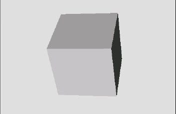
Figure 12
shows another cube with a white specular light and a specular power of
10. You can enable this in the example project by uncommenting the lines
in ResetGame that set the two new specular lighting properties. Notice
how shiny the cube looks compared with the one without specular
lighting. One of the reasons for this shininess is that specular light
affects each vertex differently, even if all the vertices of a face
point in exactly the same direction. This effect results in a much more
dynamic appearance on the rendered objects.
Try experimenting with
the specular power and see the results. As the power value increases
into the tens and hundreds, the cube starts to reflect specular light
only when its faces get closer and closer toward the light source as the
specular effect becomes more and more tightly focused.
There is one additional BasicEffect property that has an effect on specular lighting: PreferPerPixelLighting. This property defaults to false,
which results in the specular component of the lighting model being
calculated for each vertex, as we have already discussed. On objects
that have large triangles (and therefore have areas of the object where
there are no vertices nearby), this can result in some visual artifacts
that can detract from the otherwise very attractive looking specular
lighting.
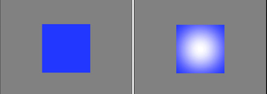
The first of these problems can be seen in the left image of Figure 13.
The image shows a cube that is facing nearly directly toward the camera
and the light source, but is slightly rotated so that the rightmost
corner is the only one that is reflecting the specular light. As you can
see, the light has a very angular look caused by the fact that only
four vertices are being used to display the entire face of the cube. The
interpolation is inaccurate due to this small number of color points.
The image on the right is of the exact same object and lighting configuration, except that PreferPerPixelLighting
has been switched on. This property instructs XNA to calculate the
specular lighting for each individual pixel that it renders, rather than
just for the vertices. As will be clearly seen, the reflection looks
much better: the angular lines have all disappeared, leaving a perfect
round highlight in its place.

The second problem with
specular lighting also occurs on objects with large triangles, but
primarily affects specular light that is very tightly focused. Figure 14
shows two images of a cube that is directly facing toward the camera
and the light source. The specular power has been set to 1000 for a very
focused effect. Because the effect is so small, it doesn't reach any of
the vertices at all. As a result, the specular light has no impact on
the face. On the right is the same scene with per pixel lighting
enabled. As each pixel then has its specular light individually
calculated, the specular light effect clearly appears within the face.
Of course, as you might
expect, there is a downside to per pixel lighting. Because the specular
component needs to be calculated for each individual pixel as opposed to
each vertex, it has a much higher processing requirement. Consider the
cubes in Figure 7-30: the visible face consists of more than 30,000 pixels, as compared with only 6 vertices.
Per pixel lighting should
therefore be used sparingly. If you have an object that is not using
specular light, has no large faces, has a low specular power, or doesn't
exhibit either of the problems discussed here, you will probably find a
performance benefit from leaving it disabled. Experiment and find which
setting provides the best balance between appearance and performance
for your game.
9.5. Emissive Light
The emissive light for
rendered objects is also most usefully set for each individual object,
so we will add a new property for this to the MatrixObjectBase class just as we did for the specular material color.
The EmissiveColor property (of type Color) can then be set within each object to control its emissive lighting settings and is applied in the MatrixObjectBase.PrepareEffect, which passes its value into the BasicEffect object's EmissiveColor property.
9.6. The Standard Lighting Rig
The lighting properties of the BasicEffect
object give you a great deal of freedom to set up your lighting system
in whatever way you want, but XNA has one additional feature that you
might find useful in your games: the standard lighting rig.
I will allow Shawn
Hargreaves, one of the Microsoft's XNA Framework developers, to explain
with the following text from his blog (which, incidentally, is a
fantastically useful resource for XNA programming and can be found at http://blogs.msdn.com/b/shawnhar/):
Many
years ago photographers discovered that a single light was not enough
to make their subjects look good. Instead, they use three.
The key light is
the brightest, and provides the main illumination and shadows. This
will typically be positioned to match a real light source such as an
overhead lamp, a window, or the sun for an outdoor scene.
The fill light is
dimmer, and usually angled at 90 degrees to the key. This is used to
soften the shadows, adding shading and definition to areas that would
otherwise be solid black.
Finally, the back light is
positioned behind the character, facing toward the camera. This
illuminates only the silhouette edges, helping the character stand out
against the background.
Because this is potentially a very useful light configuration, it can be applied to your 3D game world by simply calling the BasicEffect.EnableDefaultLighting
function. In practice, it might provide a useful set of lights, it
might provide a useful basis but require a little subsequent
modification, or it might not be suitable for your game at all. Give it a
try and see what kind of results it provides; you might just like it.
9.7. Programmatic Calculation of Normals
Earlier in this section,
we explored the calculations required to automatically calculate the
normals for a triangle within a 3D object. As a final lighting-related
addition to the game framework, let's add a function that will calculate
the normals automatically.
This will be relatively basic, and will operate within the following restrictions:
It will only generate
normals that are the same for all vertices of a triangle, so no
smoothing using normal interpolation will be supported.
It
will assume that each vertex will be either used only once or that all
of its uses will have the same vertex normal. The code could potentially
be enhanced to average out multiple uses of the same vertex, but this
enhancement is left as an exercise for the reader.
It will support only triangle lists.
As we have two
different ways of rendering triangles (a simple list of triangles or
using vertex indices), we will create two corresponding functions that
process data in these two formats. To reduce the amount of code, we will
set the two functions up so that one simply calls into the other,
allowing all the calculation to be put into just a single function.
The easiest way to
implement this efficient code approach is to get the version that takes a
simple list of triangles (without vertex indices) to build a
corresponding index array. Once this is done, the vertices and the
fabricated indices can be passed into the other function to calculate on
its behalf.
Generating indices for an
unindexed triangle list is very simple: each triangle is formed from the
next three vertices in the list, so the indices are just a sequence of
incremental numbers. The first triangle is formed from indices 0, 1, and
2; the second triangle from indices 3, 4, and 5; the third from indices
6, 7, and 8; and so on.
The code for the function that handles unindexed vertices, named CalculateVertexNormals and added to the MatrixObjectBase class, can be seen in Listing 6.
It creates an array for the indices whose length is equal to the number
of vertices. The array is then filled with sequential numbers starting
from 0, and the vertices and constructed indices array are passed into a
second overload of the same function to actually generate the normals,
which we will examine in a moment.
Example 6. Generating indices for an unindexed triangle list
public void CalculateVertexNormals(VertexPositionNormalTexture[] vertices)
    {
        short[] indices;
        short i;

        // Build an array that allows us to treat the vertices as if they were indexed.
        // As the triangles are drawn sequentially, the indexes are actually just
        // an increasing sequence of numbers: the first triangle is formed from
        // vertices 0, 1 and 2, the second triangle from vertices 3, 4 and 5, etc.

        // First create the array with an element for each vertex
        indices = new short[vertices.Length];

        // Then set the elements within the array so that each contains
        // the next sequential vertex index
        for (i = 0; i < indices.Length; i++)
        {
            indices[i] = i;
        }

        // Finally delegate to the other overload to do the work
        CalculateVertexNormals(vertices, indices);
    }
|
The second overload of the
function accepts two parameters: the vertex array and the index array.
This version of the function would be used directly if you are working
with indexed vertices, or will otherwise be called from the code in Listing 7-19 if the vertices are unindexed.
The second overload works
through the vertices in the array, using the indices to determine which
vertices are used to form each triangle within the object. Once the
vertices of each triangle have been determined, their vectors are
calculated and stored in the va and vb
variables. Their cross product is then calculated in order to determine
the triangle's normal, and the resulting vector is normalized. The
normal vector is then written into all three of the vertices that formed
the triangle.
Note that as we are
updating the vertex array that was passed in as a parameter; there is no
need to return anything from this function. The normals will be written
"in place" into the existing vertices.
The code to calculate the normals is shown in Listing 7.
Example 7. Calculating the normals for an indexed triangle list
public void CalculateVertexNormals(VertexPositionNormalTexture[] vertices,
                                                                        short[] indices)
    {
        // Vectors to describe the relationships between the vertices of the triangle
        // being processed
        Vector3 vectora;
        Vector3 vectorb;
        // The resulting normal vector
        Vector3 normal;

        // Loop for each triangle (each triangle uses three indices)
        for (int index = 0; index < indices.Length; index += 3)
        {
            // Create the a and b vectors from the vertex positions
            // First the a vector from vertices 2 and 1
            vectora = vertices[index + 2].Position - vertices[index + 1].Position;
            // Next the b vector from vertices 1 and 0
            vectorb = vertices[index + 1].Position - vertices[index + 0].Position;

            // Calculate the normal as the cross product of the two vectors
            normal = Vector3.Cross(vectora, vectorb);

            // Normalize the normal
            normal.Normalize();

            // Write the normal back into all three of the triangle vertices
            vertices[index].Normal = normal;
            vertices[index+1].Normal = normal;
            vertices[index+2].Normal = normal;
        }
    }
|
This function can simply be called after the vertex positions for an object have been calculated. If you look at the CubeObject
class in the Lighting example project, you will find that this can be
used in place of the code that manually provides the normals. Try
commenting out all the BuildVertices
code that sets the vertex normals (from the "Set the vertex normals"
comment on to the end of the function) and instead enable the call to CalculateVertexNormals. The end result is identical, but with a lot less code and a lot less effort.